Categories
New Blog
EC Fan Installation Guide: Wiring, Mounting, and Operating Precautions
November 09 , 2026Meta Description: Learn how to install an EC fan correctly, including electrical wiring, mounting requirements, control connections, commissioning checks, and operating precautions.
1. Introduction
Electronically commutated (EC) fans are widely used in ventilation equipment, commercial refrigeration, air handling units, air purification systems, industrial machinery, and other applications that require reliable airflow and adjustable speed control.
Compared with conventional fan systems, EC axial fans integrate electronic motor control into the fan assembly. Depending on the product design, an EC fan may accept AC mains input and use internal electronics to control the motor, or it may use another specified power and control arrangement. This integrated design can simplify system integration, but it also means that correct installation requires attention to both mechanical and electrical details.
An adjustable ec axial fan for ventilation should not be treated as a simple motor that can be connected to any available power supply. Input voltage, frequency, wiring terminals, grounding requirements, control signals, mounting orientation, airflow direction, and environmental conditions must all match the manufacturer's specifications.
Incorrect wiring may damage the internal controller. Poor mounting can introduce vibration, noise, or mechanical stress. Insufficient ventilation around the fan may reduce cooling performance, while moisture entering the electrical compartment can create safety and reliability risks.
This guide explains the essential steps for installing an axial fan ec, from preparation and wiring to mounting, commissioning, and maintenance. It is intended for equipment manufacturers, system integrators, maintenance technicians, and B2B buyers who need to understand the practical requirements before integrating an EC fan into their equipment.
Important safety note: Electrical installation and commissioning must be performed by qualified personnel in accordance with local electrical regulations and the exact instructions supplied with the fan. The information below is general guidance, not a substitute for the product-specific wiring diagram or installation manual.
2. Understand the EC Fan Before Installation
Before beginning installation, it is important to understand the main components and operating requirements of the selected EC fan.
An EC fan generally consists of the following components:
- Fan impeller: Produces airflow through rotating blades.
- Motor: Converts electrical energy into rotational motion.
- Electronic controller: Manages motor commutation and operating speed.
- Power connection: Supplies the specified electrical input.
- Control interface: May support 0–10 V, PWM, communication protocols, or other control methods, depending on the model.
- Protective housing and mounting structure: Support the fan and protect internal components.
The exact configuration varies by manufacturer and product series. Some models integrate the controller into the motor housing, while others use a separate controller or terminal compartment.
2.1 Check the Rated Input Voltage
The first step is to confirm that the fan's rated input voltage matches the equipment's power supply.
Depending on the model, EC fans may be designed for different single-phase or three-phase AC input ranges. Other EC motor products may use DC input. Never assume that all EC fans share the same electrical configuration.
Check the following information on the product nameplate and technical datasheet:
- Rated input voltage
- Rated frequency, where applicable
- Rated current
- Maximum input power
- Phase configuration
- Protective earth requirements
- Permitted voltage tolerance
A voltage mismatch can prevent the fan from starting, cause abnormal operation, or damage its electronic components.
For example, a fan designed for a particular AC voltage and frequency should not be connected to a different supply simply because the connector appears compatible. The electrical ratings must be verified first.
2.2 Confirm the Control Method
EC fans may provide different speed-control options. Common interfaces include:
- 0–10 V analog input
- PWM speed control
- Enable or start/stop input
- Tachometer or speed feedback
- RS485 or Modbus communication on supported models
Not every EC fan supports all these functions. Some products operate at a fixed speed or provide only limited external control.
Before connecting a control system, confirm the terminal definitions, signal voltage range, input impedance, polarity, and control logic in the product documentation.
2.3 Check the Airflow Direction
Airflow direction is an essential part of fan selection and installation.
A fan may be installed in an air intake or exhaust configuration, depending on the equipment design. The airflow direction should be confirmed using the manufacturer's markings, product drawing, or technical documentation.
Do not rely only on the appearance of the blades to determine the intended airflow direction. Different impeller designs can produce different airflow patterns.
3. EC Fan Wiring: What Should Be Checked?
Correct electrical connection is one of the most important parts of EC fan installation.
Unlike a basic two-wire DC fan, many EC fan models combine a power supply connection with separate control and feedback terminals. The number of wires and their functions depend on the product design.
3.1 Disconnect the Power Before Wiring
Before opening a terminal compartment or connecting wires:
1. Disconnect the equipment from its electrical supply.
2. Apply appropriate lockout and tagout procedures where required.
3. Verify that the circuit is de-energized using suitable test equipment.
4. Follow the manufacturer's discharge waiting time for internal capacitors.
5. Prevent accidental reconnection during installation.
Some EC fans contain internal DC-link capacitors that may retain hazardous voltage after the mains supply has been disconnected. Switching off the power does not necessarily mean that all internal components are immediately safe to touch.
For example, certain ZIEHL-ABEGG ECblue instructions specify a waiting period after disconnection because the internal DC link remains energized for a period of time. The required waiting time is model-specific.
Manualzz+1
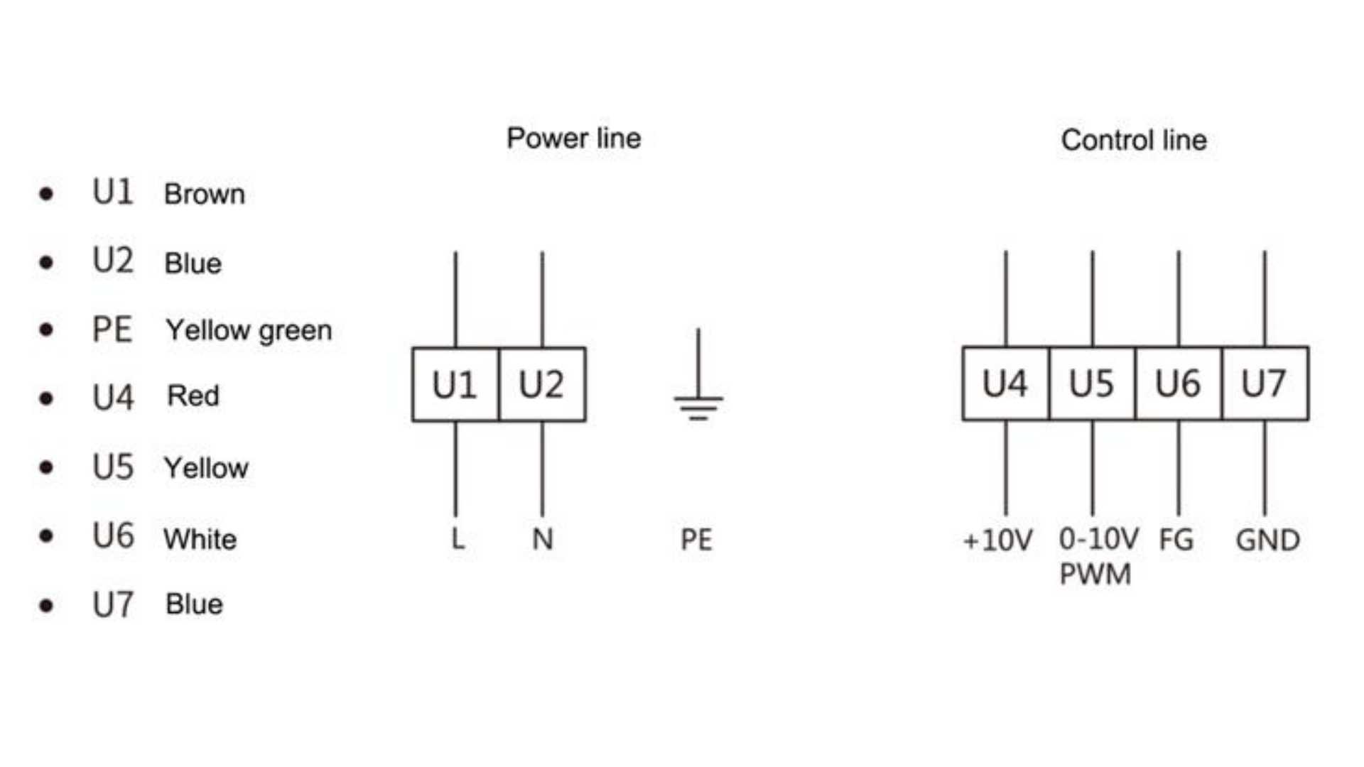
3.2 Identify the Power Terminals
The power terminals may be marked with symbols such as:
- L or L1: Line
- N: Neutral
- PE: Protective earth
- L1, L2, L3: Three-phase supply connections, where applicable
These markings are examples only. Actual terminal configurations vary by model.
Before wiring, compare the terminal labels with the manufacturer's wiring diagram. Confirm the supply type, voltage, frequency, conductor size, terminal capacity, and protective-earth requirements.
Never determine wire connections solely by wire color. Color conventions can vary between regions, cable manufacturers, and product versions.
3.3 Connect the Protective Earth Correctly
Where the product requires protective earth, the PE conductor must be connected to the designated grounding terminal.
Protective grounding helps reduce the risk of electric shock if an insulation fault occurs. The connection should follow the applicable electrical standards and the product's protection-class requirements.
Do not assume that a metal mounting frame automatically provides an adequate grounding path. The grounding arrangement must be designed and verified as part of the complete equipment installation.
3.4 Separate Power Wiring from Control Wiring
Many EC fans use low-voltage control or communication signals. These cables should be routed with appropriate separation from mains power cables to reduce electromagnetic interference.
For installations with analog speed control, PWM signals, or communication interfaces, follow the manufacturer's requirements for:
- Cable type
- Cable length
- Shielding
- Ground reference
- Routing distance
- Shield termination
For example, ZIEHL-ABEGG's ECblue instructions discuss separation between mains and control cables and provide model-specific guidance for shielded wiring.
When multiple fans are installed in one system, the wiring layout should also make maintenance and fault isolation straightforward.
3.5 Verify the Control Signal Before Power-On
If the fan supports external speed control, confirm that the control signal is compatible with the fan's input interface.
For example:
Control method Items to verify
0–10 V Voltage range, polarity, signal reference
PWM Frequency, duty-cycle range, logic level
Enable input Activation logic and permissible voltage
RS485 / Modbus A/B terminals, communication settings, wiring topology
Tachometer output Output type, voltage level, receiving circuit
Do not apply a 0–10 V signal to a terminal intended for a different function. Likewise, do not assume that PWM frequency or signal polarity is universal across EC fan models.
3.6 Do Not Use an Incompatible Variable Frequency Drive
An EC fan with an integrated electronic controller should not automatically be treated like a conventional AC motor.
Some EC fans are designed to connect directly to the specified mains supply. Supplying them from the output of an external variable frequency drive (VFD) may damage the integrated electronics or cause abnormal operation unless the manufacturer explicitly approves that arrangement.
The ebm-papst EC plug fan application guide specifically advises against powering its EC plug fans from a variable-speed drive output.
Always check the manufacturer's instructions before adding an external motor controller, inverter, or frequency converter.
4. EC Fan Mounting: Mechanical Installation Requirements
Correct mounting helps maintain airflow performance, reduce vibration, and protect the motor and bearings.
A fan that is electrically connected correctly may still perform poorly if its housing is distorted, its mounting surface is uneven, or its airflow path is obstructed.
4.1 Select a Suitable Mounting Position
Before installation, evaluate the available space and the operating environment.
Consider:
- Available installation dimensions
- Air inlet and outlet clearance
- Airflow direction
- Ambient temperature
- Humidity and condensation risk
- Dust and contaminant exposure
- Access for inspection and maintenance
The fan should be installed in a position that meets the product's permitted mounting orientations.
Some EC fans allow multiple installation orientations, while others have specific requirements for drainage, terminal-box position, or motor-axis orientation.
Do not assume that a mounting position suitable for one model is suitable for another.
4.2 Use a Flat and Stable Mounting Surface
An uneven mounting surface can place mechanical stress on the fan housing. This may distort the structure and cause the impeller to rub against stationary components.
During installation:
1. Inspect the mounting panel or bracket.
2. Remove debris and foreign objects.
3. Check that the mounting surface is flat.
4. Align the fan with the installation openings.
5. Use the specified fasteners.
6. Tighten the fasteners evenly to the manufacturer's recommended torque.
ZIEHL-ABEGG's assembly instructions emphasize avoiding structural stress and ensuring that mounting flanges or brackets are fixed on a flat, even surface.
4.3 Use the Correct Screws and Tightening Torque
Incorrect screws can damage the housing, interfere with the impeller, or reduce mounting reliability.
Before installation, check:
- Screw diameter
- Thread type
- Screw length
- Required penetration depth
- Material and strength grade
- Recommended tightening torque
Excessively long screws may extend into internal moving areas. Over-tightening may deform plastic housings or mounting brackets.
Do not use a universal torque value for every EC fan. Follow the exact product drawing or installation instructions.
4.4 Maintain Adequate Airflow Clearance
The fan needs sufficient space for air to enter and leave the impeller.
If the inlet is too close to a wall, filter, panel, or another component, airflow resistance may increase. This can reduce the actual airflow delivered by the system.
Similarly, a restricted outlet can create additional pressure losses.
For equipment designers, it is important to evaluate the complete airflow path rather than selecting a fan based only on its free-air airflow rating.
Consider the following:
- Distance between the fan inlet and nearby obstacles
- Outlet clearance
- Filter resistance
- Duct bends and transitions
- Protective grilles
- Heat exchangers and other internal components
The actual required clearance should be determined using the fan manufacturer's recommendations and the equipment's airflow design.
4.5 Check the Impeller for Free Rotation
Before connecting power, check that the impeller is free from obstruction.
Look for:
- Packaging materials
- Loose screws
- Cable ties
- Dust or debris
- Deformed blades
- Foreign objects inside the housing
Where the manufacturer's instructions permit manual inspection, verify that the impeller can rotate without scraping or abnormal resistance. Do not force the impeller or apply excessive pressure to the blades.
4.6 Consider Vibration Isolation
In equipment where noise and vibration are important, suitable mounting arrangements can help reduce vibration transmission.
Depending on the application, this may involve:
- Properly designed mounting brackets
- Suitable vibration-isolation elements
- Stable support panels
- Balanced fan assemblies
- Correct screw tightening
However, vibration isolators should not be selected without considering the fan's weight, speed, mounting orientation, and operating conditions. Excessive flexibility can create instability or additional movement.
5. Operating Precautions Before Starting an EC Fan
After completing the electrical and mechanical installation, do not immediately operate the fan at full speed. A commissioning inspection helps identify installation errors before they affect the equipment.
5.1 Inspect the Complete Installation
Before energizing the fan, confirm the following:
- The fan model matches the equipment design.
- The rated voltage and frequency match the power supply.
- All electrical terminals are correctly connected.
- Protective grounding is completed where required.
- Power and control cables are properly routed and secured.
- The fan housing is firmly mounted.
- The impeller is free from foreign objects.
- The air inlet and outlet are not blocked.
- All required safety guards are installed.
- The terminal cover and protective enclosure are properly closed.
The manufacturer's commissioning instructions should always take priority. ZIEHL-ABEGG's ECblue documentation also highlights the need to check electrical connections, remove foreign objects, and verify that required protective devices are installed before startup.
5.2 Perform a Controlled First Startup
During the first startup, keep personnel and loose objects away from the impeller and other moving components.
Observe the fan for:
- Correct starting behavior
- Unexpected vibration
- Abnormal mechanical noise
- Unusual odor or smoke
- Unexpected speed changes
- Error indicators or fault signals
- Abnormal current consumption
If the fan does not start, do not repeatedly switch the power on and off without identifying the cause. Check the supply, control signal, wiring, and fault indication according to the manufacturer's troubleshooting instructions.
5.3 Verify the Rotation and Airflow Direction
After startup, verify that the airflow moves in the intended direction.
A fan that rotates but produces airflow in the wrong direction may reduce the cooling or ventilation effectiveness of the complete system.
If the airflow direction is incorrect, stop the equipment and check the fan model, installation orientation, and manufacturer's configuration instructions. Do not attempt to reverse connections or modify wiring unless the product documentation explicitly permits it.
5.4 Check Operating Current and Temperature
Where suitable measuring equipment and procedures are available, compare the operating current and input power with the product specifications.
An unexpectedly high current may indicate:
- Incorrect supply conditions
- Excessive mechanical resistance
- An unsuitable control signal
- An installation or wiring problem
- Operation outside the specified conditions
Also check the operating environment. High ambient temperature, restricted ventilation around the controller, or excessive contamination may affect reliability.
5.5 Avoid Frequent Unnecessary Power Cycling
Some EC fan controllers include internal functions such as startup management, fault protection, and DC-link energy storage. Their restart requirements can vary by design.
Frequent switching through the mains supply may not be suitable for every EC fan. If the product supports a dedicated enable or control input, use the method specified by the manufacturer for normal operation and speed control.
Do not assume that all EC fans can be switched or controlled in the same way.
6. Common EC Fan Installation Mistakes
Even when the selected fan is technically suitable, installation mistakes can reduce performance or shorten service life.
Common mistake
Possible consequence
Recommended action
Incorrect input voltage
Startup failure or controller damage
Verify nameplate and supply
Incorrect terminal connection
Electrical fault or malfunction
Follow the exact wiring diagram
Missing protective earth
Increased electric shock risk
Complete the specified grounding
Power and signal cables routed together without consideration
Signal interference
Follow EMC wiring guidance
Uneven mounting surface
Housing distortion and impeller rubbing
Use a flat, stable mounting surface
Excessively long screws
Internal interference or mechanical damage
Follow specified screw dimensions
Restricted air inlet
Reduced airflow and increased resistance
Review inlet clearance
Blocked outlet
Reduced system performance
Check the complete airflow path
Moisture entering the terminal compartment
Corrosion or electrical failure
Follow the specified environmental protection requirements
Incompatible external VFD
Controller malfunction or damage
Confirm compatibility with the manufacturer
6.1 Why Does an EC Fan Make Abnormal Noise After Installation?
Unusual noise does not necessarily mean that the motor itself is defective.
Possible causes include:
- Impeller contact with the housing
- Loose mounting screws
- Uneven mounting surfaces
- Vibration transmitted through the equipment frame
- Air turbulence caused by nearby obstacles
- Foreign objects in the airflow path
- Operation outside the recommended speed or pressure range
The correct troubleshooting process should begin with mechanical inspection and airflow evaluation before assuming an electrical or motor fault.
6.2 Why Does an EC Fan Fail to Start?
If the fan does not start after installation, check the following areas:
1. Is the input voltage within the specified range?
2. Is the power supply correctly connected?
3. Is protective grounding completed where required?
4. Is the enable signal active, if the model requires one?
5. Is the speed-control signal within the permitted range?
6. Is the impeller mechanically obstructed?
7. Does the controller indicate a fault?
Some EC fans have built-in protective functions that stop the motor when an abnormal condition is detected. The exact protection behavior depends on the product design.
Do not repeatedly reset a fan without understanding why the protection function has activated.
7. Maintenance Recommendations for Long-Term Operation
Correct installation is only the first step. Regular inspection helps maintain reliable airflow and reduces the risk of unexpected downtime.
7.1 Clean the Fan and Airflow Path
Dust accumulation on the impeller, grille, or nearby filters may increase airflow resistance and affect fan performance.
Maintenance should include:
- Checking the impeller for dust buildup
- Cleaning the protective grille
- Inspecting filters and air passages
- Removing foreign objects
- Checking for signs of corrosion or moisture
Before cleaning, isolate the power supply and follow the manufacturer's safety instructions. Avoid allowing water or cleaning chemicals to enter the motor or electronic controller.
7.2 Inspect Cables and Terminals
Periodically check power and control cables for:
- Damaged insulation
- Loose connections
- Excessive bending
- Abrasion
- Heat discoloration
- Moisture exposure
Any damaged cable or connection should be addressed by qualified personnel using components suitable for the installation environment.
7.3 Monitor Noise and Vibration Changes
Changes in noise or vibration can indicate a developing mechanical problem.
Compare current operating conditions with the original commissioning record. If vibration increases or unusual sounds appear, inspect the mounting structure, impeller, airflow path, and bearings according to the manufacturer's maintenance guidance.
7.4 Keep the Controller Within Its Permitted Environment
The controller's temperature and environmental limits should be considered alongside the motor's operating limits.
An EC fan installed in a compact equipment enclosure may experience higher temperatures than the surrounding room. Ensure that the fan and its electronics operate within their specified ambient and installation conditions.
7.5 Establish a Maintenance Record
For commercial and industrial applications, record:
- Installation date
- Fan model and serial number
- Rated voltage and current
- Control method
- Initial operating current
- Initial noise and vibration observations
- Inspection and cleaning dates
- Any fault codes or corrective actions
A maintenance record makes it easier to identify performance changes and plan preventive maintenance.
8. How to Select an EC Fan That Is Easy to Integrate
Installation requirements should be considered before purchasing an EC fan, not only after the product arrives.
For OEM manufacturers and equipment integrators, a suitable fan should match the electrical, mechanical, airflow, and environmental requirements of the final equipment.
8.1 Confirm the Electrical Compatibility
Provide the supplier with:
- Available input voltage
- AC or DC power requirements
- Rated frequency, if applicable
- Expected current and power range
- Required control method
- Feedback or communication requirements
This information helps the supplier recommend an appropriate model and avoid electrical compatibility problems.
8.2 Confirm the Mechanical Dimensions
Check:
- Overall fan dimensions
- Mounting-hole positions
- Hole diameter
- Installation depth
- Housing material
- Connector position
- Cable exit direction
Even a small dimensional difference can create difficulties during mass production or equipment replacement.
8.3 Evaluate Airflow and Static Pressure Together
A fan's rated airflow alone does not determine whether it is suitable for an application.
The equipment's filters, ducts, grilles, heat exchangers, and internal structures create airflow resistance. Therefore, the fan should be selected according to the required operating point, considering both airflow and static pressure.
Where available, review the fan performance curve and compare it with the system resistance curve.
8.4 Consider the Operating Environment
Discuss the following conditions with the supplier:
- Ambient temperature
- Relative humidity
- Dust exposure
- Condensation risk
- Continuous operating hours
- Required noise level
- Expected service life
If the equipment operates outdoors or in a humid environment, confirm the fan's protection rating and the installation requirements for cable entries, connectors, and terminal compartments.
8.5 Request Technical Documentation
Before placing a bulk order, request the relevant documents, such as:
- Product datasheet
- Dimensional drawing
- Wiring diagram
- Performance curve
- Installation instructions
- Test reports and applicable certificates
These documents help the engineering team complete product integration and support future maintenance.
9. How China Chungfo Fan Supports EC Fan Integration
Choosing a reliable EC fan supplier is important for both initial equipment development and long-term product consistency.
China Chungfo Fan focuses on the research, development, manufacturing, and sales of cooling fans, blowers, cross-flow fans, and related motor products. Its manufacturing capabilities support customers who need fan solutions for different equipment structures and operating requirements.
For EC fan projects, communication between the supplier and the equipment manufacturer should begin before finalizing the product model.
Important project details include:
- Required voltage and electrical configuration
- Fan dimensions and mounting requirements
- Airflow and static pressure targets
- Speed-control requirements
- Noise expectations
- Operating environment
- Cable and connector requirements
- OEM customization needs
A clear technical specification helps reduce installation problems, improve compatibility, and make mass production more predictable.
For customers developing new ventilation or cooling equipment, China Chungfo Fan can discuss application requirements and help evaluate suitable fan configurations.
10. Conclusion
Correct EC fan installation involves more than connecting power cables and fixing the fan to a mounting panel. Electrical compatibility, control-signal configuration, protective grounding, mechanical alignment, airflow clearance, and environmental conditions all affect the final performance.
Before startup, verify the wiring, mounting structure, impeller clearance, safety guards, and control settings. During operation, monitor current, airflow, noise, and vibration. For long-term reliability, establish a suitable inspection and cleaning schedule.
For OEM manufacturers and equipment integrators, choosing an EC fan with compatible electrical interfaces, appropriate dimensions, suitable airflow performance, and clear technical documentation can make the installation process much easier.
A well-selected and correctly installed EC fan helps create a more reliable ventilation or cooling system.
11. Frequently Asked Questions
Q1: Can an EC fan be connected directly to an AC power supply?
Some EC fans are designed for direct connection to a specified AC mains supply because they contain integrated electronic control. However, other EC motor products may require a different power arrangement. Always confirm the rated input and wiring diagram before connection.
Q2: Do all EC fans use the same wiring colors?
No. Wire colors and terminal assignments vary between manufacturers, models, and markets. Always follow the wiring diagram supplied with the exact fan model.
Q3: Can an EC fan be controlled by a 0–10 V signal?
Some EC fans support 0–10 V speed control, but this function is not universal. Confirm the control interface, signal reference, voltage range, and terminal assignment in the product datasheet.
Q4: Why does an EC fan vibrate after installation?
Possible causes include uneven mounting, loose fasteners, impeller interference, airflow turbulence, or an unsuitable mounting structure. Inspect the mechanical installation before assuming that the motor is defective.
Q5: Can an EC fan operate continuously?
Many EC fans are designed for continuous operation within their specified electrical, thermal, and environmental limits. Confirm the permitted duty cycle and operating conditions for the selected model.
Q6: Can an external variable frequency drive control an EC fan?
Not necessarily. Many EC fans have integrated electronic controllers and are not designed to receive the output of an external VFD. Use an external drive only when the fan manufacturer explicitly confirms compatibility.
Q7: What information should I provide when ordering a customized EC fan?
Provide the required voltage, dimensions, airflow, static pressure, speed, noise level, control method, operating environment, and connector requirements. Drawings or application photos can also help the supplier evaluate the design.